


Where would you ever see a 40' long x 5' wide mass along side a railroad track? No where!
I started doing a lot of research and found there were numerous ways to control the turnouts. Most of them were expensive. Multiple expensive (about $30 per) times 14 turnouts = too much $$$. Relying on the ever useful N Scale Net site, I cam across the process of using model airplane mini servos to control the turnouts. I looked at Tam Valley Depot and saw they looked to have perfected the process. They had a great article in the July 2009 Model Railroad Hobbyist Magazine that really showed the entire process. I was also really impressed that Duncan (Tam Valley owner) pointed out, on his site, that you could get servos off Ebay in bulk for lower costs. He even described what to get off Ebay. Amazing!
Fortunately, I have a few extra turnouts and can do a little research without sacrificing the layout. I started by pulling one of them apart to see how they were built.


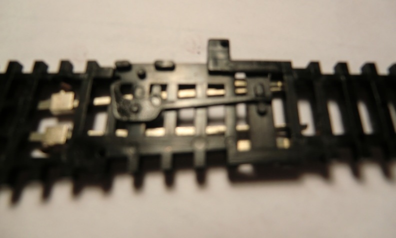 |
| Underside of the actuator mechanism |
 |
| Server under layout and brass guide tube |
 |
| Notice the longer actuator bar on the Atlas turnout |
 |
| Jeff's actuator mechanism |
Since the slide activator bar was so short, I considered having the wire run under the turnout and come up to the bottom of the slide activator:
 |
| Slot and hole added to the bottom of the actuator bar |
 |
| Slot test with wire test |

The only critical issue with this solution is getting a really good bond between the styrene extension and the activator bar. There's only a little less than 1/16" of activator bar exposed when the turnout is thrown, so no real way to lap joint. I use SC-125 acrylic adhesive which is sort of like super glue on steroids. It's the same consistency as water and dries in about 5 seconds. So far, 50 - 50 on confident bond. There won't be a lot of torque on the extension but it needs to be stable enough so as not to have a continual problem one the turnouts are in place on the layout.
Next phase of this will be the actual op test with the Tam Valley products, which are due in this week!
No comments:
Post a Comment