Been quite awhile since I posted but that doesn't mean there hasn't been progress. I've been pretty short on layout time recently but I have managed to get the control panel roughed in, with all the control switches:
It still needs a little work to get it to the finished product but it is a great addition and makes controlling the routes MUCH easier! The close up below shows the red/green lights on the track schematic that indicate which route is open. Simple to just throw a switch as a loco is making its way around the layout.
Speaking of locos - here's the latest addition. Thanks to Sheila for my Father's Day present of the infamous "Vomit Bonnet"!!!
Finally, Sheila & I took a weekend getaway to New Bern, NC & I managed to sneak in a little 1:1 scale train view. Here's the benefit of that quick stop:
Those stairs were awfully tempting but I opted to avoid a trespassing charge!
Stay tuned, more to come later on down the road!
Sunday, June 30, 2013
Sunday, March 17, 2013
To Rework or Not To Rework, that is the question....
I've mentioned before that this layout is based on the Atlas Atlantic Longhaul Lines and I read somewhere that John Sheridan (probably one of the foremost noted experts on model railroad layouts) had input in the design. In the notched area, things were bent fairly tight. The locos made their way around pretty well but there was an occasional disagreement as they tracked through the turnout heading into the reversing loop.
While installing my last turnout servo I managed to burn it out. Great. I went to the local chain hobby store and they had the same servo for $17.99, which I could get online for $3.95. I'm all for supporting the local shops but that was a little ridiculous. I went ahead and ordered a replacement online (along with a spare) which provided me with some down time in construction.
Here's the area that just wasn't tracking (OK - I know I've used that pun before but it works!):
Fortunately, I still had some spare track pieces and I decided to look at some options for this area. After some trial and error, I found what looked to be a much smoother solution:
So after several reworks, Sheila pointed out that the locos were working fine through that area so why mess with it? Well, I knew it just didn't feel right. So, earlier today the Yorktown M & S had a little demolition work take place:
Demolition required the removal of two turnout servos, two power feeders and about 8' of previously "ready to go" track. All in all, I think it was a good decision and things will ultimately run smoother.
While installing my last turnout servo I managed to burn it out. Great. I went to the local chain hobby store and they had the same servo for $17.99, which I could get online for $3.95. I'm all for supporting the local shops but that was a little ridiculous. I went ahead and ordered a replacement online (along with a spare) which provided me with some down time in construction.
Here's the area that just wasn't tracking (OK - I know I've used that pun before but it works!):
| Turnout 2 on the left and turnout 3 on the right - connected with an 11" radius |
| Rework concept for the "Notch" area |
![]() |
| Demo areas are the blue foam showing through the brown background |
More lessons learned - mostly the hard way.....
Should 9.75" radius curve pieces be outlawed?
Another novice layout mistake - using 9.75" radius curves. I knew they could be "difficult" so I limited the number I used on the layout. My first two locos were a Kato C30-7 Santa Fe (love this loco) and Bachmann EMD DD40AX. The DD40 was a great price and came with DCC included. What my novice N Scale self didn't realize is this thing was a monster - nearly a foot long!!!! My next loco was a Kato SD40-2 BNSF, which was also sweet looking. Here's a comparison of the three locos side-by-side:
I sold the Bachmann on Ebay and broke even - no loss, so that's good. It was a good loco but not for my layout. Now, back to the dreaded 9.75" radius curves.....
The reversing loop, which will be hidden under the upper deck, was about half 11" radius and half 9.75" radius. The Santa Fe C30 tracked around it with no problems. The SD40 - it was another issue. That bad boy WOULD NOT stop derailing on that loop. I knew that something had to happen so I pulled up the loop and re-installed it, with a little easier curve. Again - SD40 derailed. I rebuilt it a total of three times before I finally was able to get the SD40 around, in forward & reverse, at full speed. I know the locos will never run at full speed but I had to be sure that things would track (pun intended) once the upper deck "lid" was in place. Here's a view of the loop in question being reworked:
![]() |
| Problem reversing loop with Sheila's school bus and backhoe shown. |
In follow up research I learned that 3X a car length should be the minimum radius used & 5X is best. Now it makes sense, 40' boxcars are 3.25" long. Use the 3X factor and yu end up with the 9.75" radius.
I know that the 9.75" radius pieces have a place - but in the future, it that place won't be on my layouts!
Living on the Edge - Not Good
Been away for awhile but mostly due to job and work on the layout. Today's lesson - living on the edge isn't always a good thing ........
I was moving along really well on the servo installations and had the upper deck servo installed and moved on to the areas along the far left side and back of the layout. This required a little move of some room furniture as well as pulling the layout away from the wall. Things seemed to be really rocking along until it came to the two servos for the turnouts along the back of the layout. Atlas had the back track about an inch from the edge of the layout. I followed suit and felt like I had made good use of all the layout board real estate.I drilled the holes for the turnout actuator wires and was glad they missed the edge framing of the layout ...... or so I thought.
One note about the servos controlling the turnouts. The servo needs to be perpendicular to track so that when the actuator wire moves from side-to-side, the turnout will likewise move from side to side. When I started to install the servos, I realized that there wasn't enough clearance for the servo mounting bracket. I pondered that for a few minutes, looked at options and realized I had no choice - I had to cut clearance holes in the outer edge frame of the layout!!!!!
So - living on the edge didn't turn out so well. Fortunately, and it's a lame excuse, I'm the only one who knows the ugliness is there. The back edge is against the wall and will always be, even when the layout moves someday.
I was moving along really well on the servo installations and had the upper deck servo installed and moved on to the areas along the far left side and back of the layout. This required a little move of some room furniture as well as pulling the layout away from the wall. Things seemed to be really rocking along until it came to the two servos for the turnouts along the back of the layout. Atlas had the back track about an inch from the edge of the layout. I followed suit and felt like I had made good use of all the layout board real estate.I drilled the holes for the turnout actuator wires and was glad they missed the edge framing of the layout ...... or so I thought.
One note about the servos controlling the turnouts. The servo needs to be perpendicular to track so that when the actuator wire moves from side-to-side, the turnout will likewise move from side to side. When I started to install the servos, I realized that there wasn't enough clearance for the servo mounting bracket. I pondered that for a few minutes, looked at options and realized I had no choice - I had to cut clearance holes in the outer edge frame of the layout!!!!!
![]() |
| Ugly I know, but it was a tough job to actually get in here an get the hole cut. |
![]() |
| View from under the layout. |
Ironically, Living on the Edge is my cellphone ting tone - no joke........
Thursday, February 21, 2013
The Reversing Loop That Didn't
Been away from the blog for awhile but had a fairly productive weekend adding power feeders, buss bars under the layout and basically wiring up section after section on the lower portion of the layout. I had the reversing loop wired for awhile and added in the Digitrax AR1 Reversing Module this weekend. It seemed like a simple plug and play, until it didn't work at all. Hmmmm.... It was supposed to be a fairly simple plug and play. Essentially, this is a compute module that senses the "short" caused when the loco wheels cross into the reversing loop and automatically adjust the power to match the leg where the loco entered. In DC layouts, there is a manual switch that controls the reverse. Automatic is much nicer. Well, I turned to my never disappoint me resource of N Scale Net DCC Forum for some help.
I posted my layout schematic (which will be used on my control panel) along with some labels showing where my "A" circuit was located:
I had several suggestions for adjustments to the AR1 and then a User by the name of Heiko made a startling revelation: "Apart from your AR trouble, which you should solve anyway: The purple section is
not your reversing section. The section where you will connect A to B and B to A
is the horizontal blue track you reach when you go counter-clockwise through
your purple section - or, if you want, you can add the purple track to the part
switching it's polarity, but including the T/O between the purple and the
horizontal blue track. The purple section is "just" a siding to the black
section it follows. So the AR should not be required at all for that
section.
WOW!!!! He was right. I never realized when I converted the Atlas DC layout to my own layout, the area Atlas called the Reversing Loop - really was not working that way. I posted some replies and settled on the following rework of the layout:
I had also read (on the Digitrax site) that it's a bad idea to have the insulated gaps of a reversing loop at the end of a turnout. Well, I had my insulating gaps at the ends of a turn out on both ends of the reversing loop. The rework shown above eliminated that issue and also made a true reversing loop. The change added some length to the reversing loop, which translates into a longer train capacity. The longest train on your layout is limited to the length of the reversing loop.
The downside of this rework meant tearing up track that was nailed down and roadbed that was glued down. Had to do what I had to do. It was a couple nights of work to rework. Once I relaid the new segment of roadbed and laid the new track in, I had to go back and check all the track feeders. So far, so good. The moment of truth came when I wired up the AR1 module. I powered up the layout and the first test of the reversing loop was a complete success!!!! I had a few folks ask to see a video of the reversing loop in action so here it is:
You may notice that the loco has a millisecond of hesitation as it crosses the reversing loop insulated gap. While standing at the layout, you can actually hear the AR1 make a click sound as the loco keeps right on trucking.
Another very valuable, and somewhat painful, lesson learned.......
Tuesday, February 5, 2013
Turnout Turmoil - Part II
Not to blow my own horn, but I dove right in and soldered the wires to the connection. I ran a quick test using a regular Atlas Turnout Controller and one of my still motorized turnouts. No sense in frying the $32 Octopus before I knew I was basically configured right. Success!! I added the wires to the Octopus and it fired up, ready to go to work. As a side note, I saw a later post that said I could have just cut off the "charger" connection and had 2 wires to use. Live and learn...
I had ordered one Tam Valley Switch Wright Servo Bracket, along with one servo and one Bi-Color Fascia Control button. In looking at the servo bracket, it's a nice product and certainly holds the servo where it needs to be. On the down side, it's $4.25 each and I have 14 turnouts. Not to take anything away from Tam Valley, just not sure I want to invest the $55 on brackets. I will say that the instructions were excellent and included a full size wire bend guide. One option might be for Tam Valley to sell the bracket pieces for do it yourself assembly, thus reducing the cost. They do that with their fascia controllers. Here's the sequence showing the assembly process as I got the servo ready:
![]() |
| This is what comes in the Switch Wright Bracket package |
| SG-90 Servo in Bracket |
| Servo Horn with Music Wire (0.032") |
One note about the servo and Octopus Controller. I have never worked with servos before and I have to say, it took a little work but I think that was mostly my lack of knowledge and failure to read through the entire process before diving in. With my order, I bought the Servo Centering Tool (battery operated device that will center the servo - OK, that was obvious). I also bought the Remote Aligner which will allow the servo to be calibrated while installed in the final location and with the Octopus mounted to it's permanent location. It comes with a 7' connector cord, which will be handy once everything is in place on the layout, especially since I have a couple turnouts that will be nearly 4' from the Octopus. I spent about an hour last night learning to get the servo aligned and adjusting the left and right limits. Servos can move up to 70 degrees each side of center. With the turnout requiring only about 1/8" of travel, I need to really tighten up the range of motion. The Tam Valley instructions for the Octopus II were excellent.
At the end of Turnout Turmoil Part I - I had installed a small extension on the turnout activator bar and planned on using the side wire mount method. I reread Duncan's (owner of Tam Valley) article in the July 09 Model Railroad Hobbyist (great FREE online magazine - with every issue online). I saw a section about having the servo wire in the middle of the activator slide bar. It occurred to me - that's the way to go. Those plastic extension were going to be nothing but a potential problem down the road. I moved out with my test turnout and drilled out a small hole in the center of the activator bar. Serious lesson learned - drill from the top not the bottom. As the drill bit (hand drilled with a pin vise) came through the activator bar, it pushed off the top cap and completely trashed the turnout mechanism. Great. One turnout sacrificed. Second attempt worked great and it was on to the test bed. In order to mark the hole to be drilled, I cut the head off a push pin and ran it through the small hole. This way, when I pulled the turnout off the layout, I still had something to show me where to drill. Then, I just marked a circle around it with a Sharpie:
I pretty much knew better than to take the power drill to the cork and foam bed. I used a 1/4" bit and just spun it in my fingers to get through those two layers. Once I had the hole through the cork and foam, I used the drill to go through the 1/2" plywood base. I used the included double stick tape on the bracket and lined everything up. Once that was done, I still had about 5 - 10 minutes of fine tuning to get the throw distances correct. Overall. I think this is going to be an excellent system and it will look much more realistic than those damn chunky surface motors. The Bi-Color LED lights on the fascia controller are really cool! Red shows the "route" closed and green shows the route open. Here's a not so great quality video but it still gives a good idea on how everything works:
Thanks to all for the great encouragement I've been getting. I recently discovered the N Scale Model Trains group over on Facebook and have had some great suggestions. I just added a Follow Me by Email link to the Blog. If you like what you see, and want to see future updates, go ahead and add your email address.
One last detail I just remembered - if I ever decide to get really advanced, the Octopus III is adaptable with a DCC decoder. Not sure I'm up to running DCC turnout control - but the option is there.
Sunday, February 3, 2013
Turnout Turmoil
Where would you ever see a 40' long x 5' wide mass along side a railroad track? No where!
I started doing a lot of research and found there were numerous ways to control the turnouts. Most of them were expensive. Multiple expensive (about $30 per) times 14 turnouts = too much $$$. Relying on the ever useful N Scale Net site, I cam across the process of using model airplane mini servos to control the turnouts. I looked at Tam Valley Depot and saw they looked to have perfected the process. They had a great article in the July 2009 Model Railroad Hobbyist Magazine that really showed the entire process. I was also really impressed that Duncan (Tam Valley owner) pointed out, on his site, that you could get servos off Ebay in bulk for lower costs. He even described what to get off Ebay. Amazing!
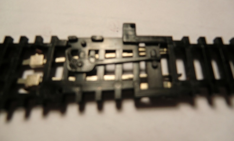
Fortunately, I have a few extra turnouts and can do a little research without sacrificing the layout. I started by pulling one of them apart to see how they were built.
![]() |
| Underside of the actuator mechanism |
![]() |
| Server under layout and brass guide tube |
![]() |
| Notice the longer actuator bar on the Atlas turnout |
![]() |
| Jeff's actuator mechanism |
Since the slide activator bar was so short, I considered having the wire run under the turnout and come up to the bottom of the slide activator:
![]() |
| Slot and hole added to the bottom of the actuator bar |
![]() |
| Slot test with wire test |
The only critical issue with this solution is getting a really good bond between the styrene extension and the activator bar. There's only a little less than 1/16" of activator bar exposed when the turnout is thrown, so no real way to lap joint. I use SC-125 acrylic adhesive which is sort of like super glue on steroids. It's the same consistency as water and dries in about 5 seconds. So far, 50 - 50 on confident bond. There won't be a lot of torque on the extension but it needs to be stable enough so as not to have a continual problem one the turnouts are in place on the layout.
Next phase of this will be the actual op test with the Tam Valley products, which are due in this week!
Subscribe to:
Posts (Atom)